a-simple-triangle / Part 10 - OpenGL render mesh
Marcel Braghetto 25 April 2019

So here we are, 10 articles in and we are yet to see a 3D model on the screen. We spent valuable effort in part 9 to be able to load a model into memory, so let’s forge ahead and start rendering it.
This article will cover some of the basic steps we need to perform in order to take a bundle of vertices and indices - which we modelled as the ast::Mesh class - and hand them over to the graphics hardware to be rendered. Here’s what we will be doing:
- Explore the OpenGL Shader Language (GLSL) and identify why it is critical to us if we want to render anything at all. We will write some code to load shader files to be used during the rendering pipeline.
- Gain a basic understanding of what a Vertex Buffer Object (VBO) is and what purpose it serves us. We will write some code to take an
ast::Mesh and generate an OpenGL flavoured mesh object which will use VBOs, then use the OpenGL mesh as the source for rendering.
- Author a simple
camera class that will contribute to the rendering pipeline which will configure where the virtual eye of our world should be.
OpenGL Shader Language (GLSL)
I have to be honest, for many years (probably around when Quake 3 was released which was when I first heard the word Shader), I was totally confused about what shaders were. Although in year 2000 (long time ago huh?) I had authored a top down C++/OpenGL helicopter shooter as my final student project for the multimedia course I was studying (it was named Chopper2k) I don’t think I had ever heard of shaders because OpenGL at the time didn’t require them. In more modern graphics - at least for both OpenGL and Vulkan - we use shaders to render 3D geometry.
A shader is typically made of two parts:
Vertex shader: this is a GLSL script which will run for every vertex and is responsible for putting a vertex into its correct position in 3D space, and to pass output data into the fragment shader. The vertex shader will almost certainly take input data from our main application code including data about each vertex of our mesh object to render which represents where in space it should be positioned and viewed from.Fragment shader: this is a GLSL script which will run for every pixel and is responsible for painting the correct colours onto the surface of the 3D representation. It will take input data from the vertex shader to help it perform this role and passes its resulting colour information as output to the graphics system to be drawn to the screen.
Spend some time browsing the ShaderToy site where you can check out a huge variety of example shaders - some of which are insanely complex. If you’ve ever wondered how games can have cool looking water or other visual effects, its highly likely it is through the use of custom shaders. Seriously, check out something like this which is done with shader code - wow…
Our humble application will not aim for the stars (yet!) but we will need at least the most basic OpenGL shader to be able to draw the vertices of our 3D models. So we shall create a shader that will be lovingly known from this point on as the default shader…
Writing the default vertex shader
To write our default shader, we will need two new plain text files - one for the vertex shader and one for the fragment shader. We need to load them at runtime so we will put them as assets into our shared assets folder so they are bundled up with our application when we do a build.
For those who have experience writing shaders you will notice that the shader we are about to write uses an older style of GLSL, whereby it uses fields such as uniform, attribute and varying, instead of more modern fields such as layout etc. The reason for this was to keep OpenGL ES2 compatibility which I have chosen as my baseline for the OpenGL implementation. Use this official reference as a guide to the GLSL language version I’ll be using in this series: https://www.khronos.org/registry/OpenGL/specs/gl/GLSLangSpec.1.10.pdf.
You could write multiple shaders for different OpenGL versions but frankly I can’t be bothered for the same reasons I explained in part 1 of this series around not explicitly supporting OpenGL ES3 due to only a narrow gap between hardware that can run OpenGL and hardware that can run Vulkan. For your own projects you may wish to use the more modern GLSL shader version language if you are willing to drop older hardware support, or write conditional code in your renderer to accommodate both.
Create new folders to hold our shader files under our main assets folder:
main/assets/shaders/opengl
Create two new text files in that folder named default.vert and default.frag. It actually doesn’t matter at all what you name shader files but using the .vert and .frag suffixes keeps their intent pretty obvious and keeps the vertex and fragment shader files grouped naturally together in the file system.
The default.vert file will be our vertex shader script. Open it in Visual Studio Code.
Note: The content of the assets folder won’t appear in our Visual Studio Code workspace. You will need to manually open the shader files yourself.
Edit default.vert with the following script:
Note: If you have written GLSL shaders before you may notice a lack of the #version ... line in the following scripts. I have deliberately omitted that line and I’ll loop back onto it later in this article to explain why.
uniform mat4 mvp;

attribute vec3 vertexPosition;

varying vec4 fragmentColor;

void main()
{
    gl_Position = mvp * vec4(vertexPosition, 1.0);
    fragmentColor = vec4(1.0, 1.0, 1.0, 1.0);
}
Let’s step through this file a line at a time.
Uniform field
A uniform field represents a piece of input data that must be passed in from the application code for an entire primitive (not per vertex). Check the official documentation under the section 4.3 Type Qualifiers https://www.khronos.org/registry/OpenGL/specs/gl/GLSLangSpec.1.10.pdf. In our vertex shader, the uniform is of the data type mat4 which represents a 4x4 matrix. We’ve named it mvp which stands for model, view, projection - it describes the transformation to apply to each vertex passed in so it can be positioned in 3D space correctly. The shader script is not permitted to change the values in uniform fields so they are effectively read only.
Rather than me trying to explain how matrices are used to represent 3D data, I’d highly recommend reading this article, especially the section titled The Model, View and Projection matrices: https://www.opengl-tutorial.org/beginners-tutorials/tutorial-3-matrices.
In our rendering code, we will need to populate the mvp uniform with a value which will come from the current transformation of the mesh we are rendering, combined with the properties of the camera which we will create a little later in this article.
Without providing this matrix, the renderer won’t know where our eye is in the 3D world, or what direction it should be looking at, nor will it know about any transformations to apply to our vertices for the current mesh.
Attribute field
attribute vec3 vertexPosition;
An attribute field represents a piece of input data from the application code to describe something about each vertex being processed. In our case we will be sending the position of each vertex in our mesh into the vertex shader so the shader knows where in 3D space the vertex should be. The shader script is not permitted to change the values in attribute fields so they are effectively read only.
Varying field
varying vec4 fragmentColor;
A varying field represents a piece of data that the vertex shader will itself populate during its main function - acting as an output field for the vertex shader. This field then becomes an input field for the fragment shader. In our shader we have created a varying field named fragmentColor - the vertex shader will assign a value to this field during its main function and as you will see shortly the fragment shader will receive the field as part of its input data. This is how we pass data from the vertex shader to the fragment shader.
Main function
void main()
{
    gl_Position = mvp * vec4(vertexPosition, 1.0);
    fragmentColor = vec4(1.0, 1.0, 1.0, 1.0);
}
The main function is what actually executes when the shader is run.
GLSL has some built in functions that a shader can use such as the gl_Position shown above. For the version of GLSL scripts we are writing you can refer to this reference guide to see what is available in our shader scripts: https://www.khronos.org/registry/OpenGL/specs/gl/GLSLangSpec.1.10.pdf. Check the section named Built in variables to see where the gl_Position command comes from.
Our vertex shader main function will do the following two operations each time it is invoked:
- Set the built in
gl_Position field to our model, view , projection 4x4 matrix multiplied by the given input vertexPosition (x, y, z) vector.
- Assign a value to the
fragmentColor field which will be passed along to the fragment shader. For now we are hard coding a colour of white (Red: 1.0, Green 1.0, Blue: 1.0, Alpha: 1.0).
Writing the default fragment shader
A vertex shader is always complemented with a fragment shader. Edit the default.frag file with the following:
varying vec4 fragmentColor;

void main()
{
    gl_FragColor = fragmentColor;
}
Varying field
varying vec4 fragmentColor;
In our fragment shader we have a varying field named fragmentColor. Recall that our vertex shader also had the same varying field. In the fragment shader this field will be the input that complements the vertex shaders output - in our case the colour white.
Main function
void main()
{
    gl_FragColor = fragmentColor;
}
Our fragment shader will use the gl_FragColor built in property to express what display colour the pixel should have. It is calculating this colour by using the value of the fragmentColor varying field.
Note: I use color in code but colour in editorial writing as my native language is Australian English (pretty much British English) - it’s not just me being randomly inconsistent!
Shader versions
A shader must have a #version line at the top of its script file to tell OpenGL what flavour of the GLSL language to expect. The shader files we just wrote don’t have this line - but there is a reason for this.
If our application is running on a device that uses desktop OpenGL, the version lines for the vertex and fragment shaders might look like these:
Desktop OpenGL vertex shader
Desktop OpenGL fragment shader
However, if our application is running on a device that only supports OpenGL ES2, the versions might look like these:
OpenGL ES2 vertex shader
OpenGL ES2 fragment shader
#version 100
precision mediump float
Here is a link that has a brief comparison of the basic differences between ES2 compatible shaders and more modern shaders: https://github.com/mattdesl/lwjgl-basics/wiki/GLSL-Versions.
The problem is that we can’t get the GLSL scripts to conditionally include a #version string directly - the GLSL parser won’t allow conditional macros to do this. To get around this problem we will omit the versioning from our shader script files and instead prepend them in our C++ code when we load them from storage, but before they are processed into actual OpenGL shaders. We will base our decision of which version text to prepend on whether our application is compiling for an ES2 target or not at build time. We will write the code to do this next.
Loading our shader
Before we start writing our shader code, we need to update our graphics-wrapper.hpp header file to include a marker indicating whether we are running on desktop OpenGL or ES2 OpenGL. Edit your graphics-wrapper.hpp and add a new macro #define USING_GLES to the three platforms that only support OpenGL ES2 (Emscripten, iOS, Android). We will use this macro definition to know what version text to prepend to our shader code when it is loaded.
#pragma once

#if defined(__EMSCRIPTEN__)
#include <GLES2/gl2.h>
#define USING_GLES
#elif __APPLE__
#define GL_SILENCE_DEPRECATION
#include "TargetConditionals.h"
#if TARGET_OS_IPHONE
#include <OpenGLES/ES2/gl.h>
#define USING_GLES
#else
#include <OpenGL/gl3.h>
#endif
#elif __ANDROID__
#include <GLES2/gl2.h>
#define USING_GLES
#elif WIN32
#define GLEW_STATIC
#include <GL/glew.h>
#endif
There are many examples of how to load shaders in OpenGL, including a sample on the official reference site https://www.khronos.org/opengl/wiki/Shader_Compilation. We will use some of this information to cultivate our own code to load and store an OpenGL shader from our GLSL files.
We are going to author a new class which is responsible for encapsulating an OpenGL shader program which we will call a pipeline. It will include the ability to load and process the appropriate shader source files and to destroy the shader program itself when it is no longer needed. We’ll call this new class OpenGLPipeline. Create the following new files:
main/src/application/opengl/opengl-pipeline.hppmain/src/application/opengl/opengl-pipeline.cpp
Header file
Edit the opengl-pipeline.hpp header with the following:
#pragma once

#include "../../core/graphics-wrapper.hpp"
#include "../../core/internal-ptr.hpp"
#include <string>

namespace ast
{
    struct OpenGLPipeline
    {
        OpenGLPipeline(const std::string& shaderName);

    private:
        struct Internal;
        ast::internal_ptr<Internal> internal;
    };
} // namespace ast
Our header file will make use of our internal_ptr to keep the gory details about shaders hidden from the world. The constructor for this class will require the shader name as it exists within our assets folder amongst our OpenGL shader files. If we wanted to load the shader represented by the files assets/shaders/opengl/default.vert and assets/shaders/opengl/default.frag we would pass in "default" as the shaderName parameter.
The header doesn’t have anything too crazy going on - the hard stuff is in the implementation.
Edit the opengl-pipeline.cpp implementation with the following (theres a fair bit!):
#include "opengl-pipeline.hpp"
#include "../../core/assets.hpp"
#include "../../core/log.hpp"
#include <stdexcept>
#include <vector>

using ast::OpenGLPipeline;

namespace
{
    GLuint compileShader(const GLenum& shaderType, const std::string& shaderSource)
    {
        const std::string logTag{"ast::OpenGLPipeline::compileShader"};
        GLuint shaderId{glCreateShader(shaderType)};

        const char* shaderData{shaderSource.c_str()};
        glShaderSource(shaderId, 1, &shaderData, nullptr);
        glCompileShader(shaderId);

        GLint shaderCompilationResult;
        glGetShaderiv(shaderId, GL_COMPILE_STATUS, &shaderCompilationResult);

        if (!shaderCompilationResult)
        {
            GLint errorMessageLength;
            glGetShaderiv(shaderId, GL_INFO_LOG_LENGTH, &errorMessageLength);
            std::vector<char> errorMessage(errorMessageLength + 1);
            glGetShaderInfoLog(shaderId, errorMessageLength, nullptr, &errorMessage[0]);
            ast::log(logTag, &errorMessage[0]);
            throw std::runtime_error(logTag + "Shader failed to compile.");
        }

        return shaderId;
    }

    GLuint createShaderProgram(const std::string& shaderName)
    {
        const std::string logTag{"ast::OpenGLPipeline::createShaderProgram"};

        ast::log(logTag, "Creating pipeline for '" + shaderName + "'");

        const std::string vertexShaderCode{ast::assets::loadTextFile("assets/shaders/opengl/" + shaderName + ".vert")};
        const std::string fragmentShaderCode{ast::assets::loadTextFile("assets/shaders/opengl/" + shaderName + ".frag")};

#ifdef USING_GLES
        std::string vertexShaderSource{"#version 100\n" + vertexShaderCode};
        std::string fragmentShaderSource{"#version 100\nprecision mediump float;\n" + fragmentShaderCode};
#else
        std::string vertexShaderSource{"#version 120\n" + vertexShaderCode};
        std::string fragmentShaderSource{"#version 120\n" + fragmentShaderCode};
#endif

        GLuint shaderProgramId{glCreateProgram()};
        GLuint vertexShaderId{::compileShader(GL_VERTEX_SHADER, vertexShaderSource)};
        GLuint fragmentShaderId{::compileShader(GL_FRAGMENT_SHADER, fragmentShaderSource)};

        glAttachShader(shaderProgramId, vertexShaderId);
        glAttachShader(shaderProgramId, fragmentShaderId);
        glLinkProgram(shaderProgramId);

        GLint shaderProgramLinkResult;
        glGetProgramiv(shaderProgramId, GL_LINK_STATUS, &shaderProgramLinkResult);

        if (!shaderProgramLinkResult)
        {
            GLint errorMessageLength;
            glGetProgramiv(shaderProgramId, GL_INFO_LOG_LENGTH, &errorMessageLength);
            std::vector<char> errorMessage(errorMessageLength + 1);
            glGetProgramInfoLog(shaderProgramId, errorMessageLength, nullptr, &errorMessage[0]);
            ast::log(logTag, &errorMessage[0]);
            throw std::runtime_error(logTag + "Shader program failed to compile.");
        }

        glDetachShader(shaderProgramId, vertexShaderId);
        glDetachShader(shaderProgramId, fragmentShaderId);
        glDeleteShader(vertexShaderId);
        glDeleteShader(fragmentShaderId);

        return shaderProgramId;
    }
} // namespace

struct OpenGLPipeline::Internal
{
    const GLuint shaderProgramId;
    const GLuint uniformLocationMVP;
    const GLuint attributeLocationVertexPosition;

    Internal(const std::string& shaderName)
        : shaderProgramId(::createShaderProgram(shaderName)),
          uniformLocationMVP(glGetUniformLocation(shaderProgramId, "mvp")),
          attributeLocationVertexPosition(glGetAttribLocation(shaderProgramId, "vertexPosition")) {}

    ~Internal()
    {
        glDeleteProgram(shaderProgramId);
    }
};

OpenGLPipeline::OpenGLPipeline(const std::string& shaderName)
    : internal(ast::make_internal_ptr<Internal>(shaderName)) {}
There is a lot to digest here but the overall flow hangs together like this:
- Someone creates a new instance of our
ast::OpenGLPipeline class, giving the name of the shader to load.
- Internally the name of the shader is used to load the
.vert and .frag text files into shader source strings, ready to be fed into the OpenGL shader parser.
- Depending on whether we are in a desktop or ES2 version of OpenGL, the source strings are prefixed with the appropriate
#version data before being parsed by OpenGL.
- We then ask OpenGL to create a new empty shader program, which it returns to us via a unique OpenGL ID. This ID is of type
GLuint and we will hold onto it so our destructor can use it during clean up.
- After obtaining an empty shader program we then ask OpenGL to compile our vertex shader source string, then the fragment shader source string into OpenGL shader objects. OpenGL will hand us back a unique ID for each of the compiled shader objects.
- After obtaining the compiled shader IDs, we ask OpenGL to attach and then link them into our shader program.
- We perform some error checking to make sure that the shaders were able to compile and link successfully - logging any errors through our logging system.
- If the shader program compiled and linked without problem we then detach and discard the compiled shader objects as they are no longer needed after the linking stage.
- After we have successfully created a fully linked shader program, we query it for where to find our
mvp uniform and our vertexPosition attribute shader fields. We do this so later during rendering we know how to insert the data into them from our application code. Remember, the uniform and attribute fields are input fields - meaning we have to provide their data values through our rendering code ourselves.
Although it will make this article a bit longer, I think I’ll walk through this code in detail to describe how it maps to the flow above.
Internal struct
The Internal struct implementation basically does three things:
- Request that a new OpenGL shader program is created with the supplied
shaderName parameter and keep a reference to its ID.
- Query the created shader program to find the locations where our
uniform and attribute fields are. We store these locations so we don’t have to look them up again during rendering.
- Upon destruction we will ask OpenGL to delete the shader program that was created during initialisation.
Note: At this level of implementation don’t get confused between a shader program and a shader - they are different things. A shader program is what we need during rendering and is composed by attaching and linking multiple compiled shader objects.
struct OpenGLPipeline::Internal
{
    const GLuint shaderProgramId;
    const GLuint uniformLocationMVP;
    const GLuint attributeLocationVertexPosition;

    Internal(const std::string& shaderName)
        : shaderProgramId(::createShaderProgram(shaderName)),
          uniformLocationMVP(glGetUniformLocation(shaderProgramId, "mvp")),
          attributeLocationVertexPosition(glGetAttribLocation(shaderProgramId, "vertexPosition")) {}

    ~Internal()
    {
        glDeleteProgram(shaderProgramId);
    }
};
- Creating the
shaderProgramId is deferred to the ::createShaderProgram(shaderName) function which I’ll show in a minute.
- The
uniformLocationMVP property is populated using the glGetUniformLocation OpenGL command, passing in the shader program ID to query along with the string literal name of the field to locate in the shader code.
- The
attributeLocationVertexPosition property is populated using the glGetAttribLocation OpenGL command, passing in the shader program ID to query along with the string literal name of the field to locate in the shader code.
- The OpenGL
glDeleteProgram command is called in the destructor to free up the shader program when the pipeline instance goes out of scope.
The createShaderProgram function
This function is responsible for taking a shader name, then loading, processing and linking the shader script files into an instance of an OpenGL shader program. Let’s dissect this function:
GLuint createShaderProgram(const std::string& shaderName)
{
    const std::string logTag{"ast::OpenGLPipeline::createShaderProgram"};

    ast::log(logTag, "Creating pipeline for '" + shaderName + "'");

    const std::string vertexShaderCode{ast::assets::loadTextFile("assets/shaders/opengl/" + shaderName + ".vert")};
    const std::string fragmentShaderCode{ast::assets::loadTextFile("assets/shaders/opengl/" + shaderName + ".frag")};
We start by loading up the vertex and fragment shader text files into strings. You can see that we create the strings vertexShaderCode and fragmentShaderCode to hold the loaded text content for each one. For our OpenGL application we will assume that all shader files can be found at assets/shaders/opengl. We also assume that both the vertex and fragment shader file names are the same, except for the suffix where we assume .vert for a vertex shader and .frag for a fragment shader.
#ifdef USING_GLES
    std::string vertexShaderSource{"#version 100\n" + vertexShaderCode};
    std::string fragmentShaderSource{"#version 100\nprecision mediump float;\n" + fragmentShaderCode};
#else
    std::string vertexShaderSource{"#version 120\n" + vertexShaderCode};
    std::string fragmentShaderSource{"#version 120\n" + fragmentShaderCode};
#endif
Recall that earlier we added a new #define USING_GLES macro in our graphics-wrapper.hpp header file which was set for any platform that compiles against OpenGL ES2 instead of desktop OpenGL. We are now using this macro to figure out what text to insert for the shader version.
For desktop OpenGL we insert the following for both the vertex and shader fragment text:
For OpenGL ES2 we insert the following for the vertex shader text:
and for the fragment shader text:
#version 100
precision mediump float;
Notice that the version code is different between the two variants, and for ES2 systems we are adding the precision mediump float;. This is a precision qualifier and for ES2 - which includes WebGL - we will use the mediump format for the best compatibility. For more information on this topic, see Section 4.5.2: Precision Qualifiers in this link: https://www.khronos.org/files/opengles_shading_language.pdf
Next we ask OpenGL to create a new empty shader program by invoking the glCreateProgram() command. OpenGL will return to us a GLuint ID which acts as a handle to the new shader program.
We then use our function ::compileShader(const GLenum& shaderType, const std::string& shaderSource) to take each type of shader to compile - GL_VERTEX_SHADER and GL_FRAGMENT_SHADER - along with the appropriate shader source strings to generate OpenGL compiled shaders from them. Upon compiling the input strings into shaders, OpenGL will return to us a GLuint ID each time which act as handles to the compiled shaders.
GLuint shaderProgramId{glCreateProgram()};
GLuint vertexShaderId{::compileShader(GL_VERTEX_SHADER, vertexShaderSource)};
GLuint fragmentShaderId{::compileShader(GL_FRAGMENT_SHADER, fragmentShaderSource)};
I’ll walk through the ::compileShader function when we have finished our current function dissection.
An OpenGL compiled shader on its own doesn’t give us anything we can use in our renderer directly. We must take the compiled shaders (one for vertex, one for fragment) and attach them to our shader program instance via the OpenGL command glAttachShader. After we have attached both shaders to the shader program, we then ask OpenGL to link the shader program using the glLinkProgram command. When the shader program has successfully linked its attached shaders we have a fully operational OpenGL shader program that we can use in our renderer.
glAttachShader(shaderProgramId, vertexShaderId);
glAttachShader(shaderProgramId, fragmentShaderId);
glLinkProgram(shaderProgramId);
However if something went wrong during this process we should consider it to be a fatal error (well, I am going to do that anyway). This brings us to a bit of error handling code:
GLint shaderProgramLinkResult;
glGetProgramiv(shaderProgramId, GL_LINK_STATUS, &shaderProgramLinkResult);

if (!shaderProgramLinkResult)
{
    GLint errorMessageLength;
    glGetProgramiv(shaderProgramId, GL_INFO_LOG_LENGTH, &errorMessageLength);
    std::vector<char> errorMessage(errorMessageLength + 1);
    glGetProgramInfoLog(shaderProgramId, errorMessageLength, nullptr, &errorMessage[0]);
    ast::log(logTag, &errorMessage[0]);
    throw std::runtime_error(logTag + "Shader program failed to compile.");
}
This code simply requests the linking result of our shader program through the glGetProgramiv command along with the GL_LINK_STATUS type. If the result is unsuccessful, we will extract whatever error logging data might be available from OpenGL, print it through our own logging system then deliberately throw a runtime exception.
Assuming we don’t have any errors, we still need to perform a small amount of clean up before returning our newly generated shader program handle ID. Once a shader program has been successfully linked, we no longer need to keep the individual compiled shaders, so we detach each compiled shader using the glDetachShader command, then delete the compiled shader objects using the glDeleteShader command. Notice how we are using the ID handles to tell OpenGL what object to perform its commands on.
glDetachShader(shaderProgramId, vertexShaderId);
glDetachShader(shaderProgramId, fragmentShaderId);
glDeleteShader(vertexShaderId);
glDeleteShader(fragmentShaderId);
We finally return the ID handle of the created shader program to the original caller of the ::createShaderProgram function.
The compileShader function
This function is called twice inside our createShaderProgram function, once to compile the vertex shader source and once to compile the fragment shader source. Let’s dissect it.
We start off by asking OpenGL to create an empty shader (not to be confused with a shader program) with the given shaderType via the glCreateShader command. OpenGL will return to us an ID that acts as a handle to the new shader object.
GLuint compileShader(const GLenum& shaderType, const std::string& shaderSource)
{
    const std::string logTag{"ast::OpenGLPipeline::compileShader"};
    GLuint shaderId{glCreateShader(shaderType)};
We take our shaderSource string, wrapped as a const char* to allow it to be passed into the OpenGL glShaderSource command. The glShaderSource command will associate the given shader object with the string content pointed to by the shaderData pointer. We then invoke the glCompileShader command to ask OpenGL to take the shader object and using its source, attempt to parse and compile it.
const char* shaderData{shaderSource.c_str()};
glShaderSource(shaderId, 1, &shaderData, nullptr);
glCompileShader(shaderId);
Of course in a perfect world we will have correctly typed our shader scripts into our shader files without any syntax errors or mistakes, but I guarantee that you will accidentally have errors in your shader files as you are developing them. Smells like we need a bit of error handling - especially for problems with shader scripts as they can be very opaque to identify:
GLint shaderCompilationResult;
glGetShaderiv(shaderId, GL_COMPILE_STATUS, &shaderCompilationResult);

if (!shaderCompilationResult)
{
    GLint errorMessageLength;
    glGetShaderiv(shaderId, GL_INFO_LOG_LENGTH, &errorMessageLength);
    std::vector<char> errorMessage(errorMessageLength + 1);
    glGetShaderInfoLog(shaderId, errorMessageLength, nullptr, &errorMessage[0]);
    ast::log(logTag, &errorMessage[0]);
    throw std::runtime_error(logTag + "Shader failed to compile.");
}
Here we are simply asking OpenGL for the result of the GL_COMPILE_STATUS using the glGetShaderiv command. If the result was unsuccessful, we will extract any logging information from OpenGL, log it through own own logging system, then throw a runtime exception. Being able to see the logged error messages is tremendously valuable when trying to debug shader scripts.
Finally, we will return the ID handle to the new compiled shader program to the original caller:
Creating our new default pipeline
With our new pipeline class written, we can update our existing OpenGL application code to create one when it starts. Edit your opengl-application.cpp file. First up, add the header file for our new class:
#include "opengl-pipeline.hpp"
In our Internal struct, add a new ast::OpenGLPipeline member field named defaultPipeline and assign it a value during initialisation using "default" as the shader name:
struct OpenGLApplication::Internal
{
    SDL_Window* window;
    SDL_GLContext context;
    const ast::OpenGLPipeline defaultPipeline;
    const ast::Mesh mesh;

    Internal() : window(ast::sdl::createWindow(SDL_WINDOW_OPENGL | SDL_WINDOW_RESIZABLE | SDL_WINDOW_ALLOW_HIGHDPI)),
                 context(::createContext(window)),
                 defaultPipeline(ast::OpenGLPipeline("default")),
                 mesh(ast::assets::loadOBJFile("assets/models/crate.obj"))
    {
        ast::log("CRATE!", "Crate has " + std::to_string(mesh.getVertices().size()) + " vertices and " + std::to_string(mesh.getIndices().size()) + " indices.");
    }

    ...
Run your program and ensure that our application still boots up successfully. If everything is working OK, our OpenGL application will now have a default shader pipeline ready to be used for our rendering and you should see some log output that looks like this:
ast::OpenGLPipeline::createShaderProgram: Creating pipeline for 'default'
Before continuing, take the time now to visit each of the other platforms (don’t forget to run the setup.sh for the iOS and MacOS platforms to pick up the new C++ files we added) and ensure that we are seeing the same result for each one.
OpenGL Vertex Buffer Objects (VBOs)
Now that we have our default shader program pipeline sorted out, the next topic to tackle is how we actually get all the vertices and indices in an ast::Mesh object into OpenGL so it can render them. OpenGL has no idea what an ast::Mesh object is - in fact its really just an abstraction for our own benefit for describing 3D geometry. OpenGL provides a mechanism for submitting a collection of vertices and indices into a data structure that it natively understands. The data structure is called a Vertex Buffer Object, or VBO for short. Here is the link I provided earlier to read more about them: https://www.khronos.org/opengl/wiki/Vertex_Specification#Vertex_Buffer_Object.
We will be using VBOs to represent our mesh to OpenGL. Technically we could have skipped the whole ast::Mesh class and directly parsed our crate.obj file into some VBOs, however I deliberately wanted to model a mesh in a non API specific way so it is extensible and can easily be used for other rendering systems such as Vulkan. Now we need to write an OpenGL specific representation of a mesh, using our existing ast::Mesh as an input source. We will name our OpenGL specific mesh ast::OpenGLMesh.
Author the OpenGLMesh class
Let’s get started and create two new files: main/src/application/opengl/opengl-mesh.hpp and main/src/application/opengl/opengl-mesh.cpp
Edit the opengl-mesh.hpp with the following:
#include "../../core/internal-ptr.hpp"
#include "../../core/mesh.hpp"

namespace ast
{
    struct OpenGLMesh
    {
        OpenGLMesh(const ast::Mesh& mesh);

    private:
        struct Internal;
        ast::internal_ptr<Internal> internal;
    };
} // namespace ast
Pretty basic header, the constructor will expect to be given an ast::Mesh object for initialisation.
Edit the opengl-mesh.cpp implementation with the following:
#include "opengl-mesh.hpp"
#include "../../core/glm-wrapper.hpp"
#include "../../core/graphics-wrapper.hpp"
#include <vector>

using ast::OpenGLMesh;

namespace
{
    GLuint createVertexBuffer(const ast::Mesh& mesh)
    {
        std::vector<glm::vec3> positions;

        for (const auto& vertex : mesh.getVertices())
        {
            positions.push_back(vertex.position);
        }

        GLuint bufferId;
        glGenBuffers(1, &bufferId);
        glBindBuffer(GL_ARRAY_BUFFER, bufferId);
        glBufferData(GL_ARRAY_BUFFER,
                     positions.size() * sizeof(glm::vec3),
                     positions.data(),
                     GL_STATIC_DRAW);

        return bufferId;
    }

    GLuint createIndexBuffer(const ast::Mesh& mesh)
    {
        GLuint bufferId;
        glGenBuffers(1, &bufferId);
        glBindBuffer(GL_ELEMENT_ARRAY_BUFFER, bufferId);
        glBufferData(GL_ELEMENT_ARRAY_BUFFER,
                     mesh.getIndices().size() * sizeof(uint32_t),
                     mesh.getIndices().data(),
                     GL_STATIC_DRAW);

        return bufferId;
    }
} // namespace

struct OpenGLMesh::Internal
{
    const GLuint bufferIdVertices;
    const GLuint bufferIdIndices;
    const uint32_t numIndices;

    Internal(const ast::Mesh& mesh)
        : bufferIdVertices(::createVertexBuffer(mesh)),
          bufferIdIndices(::createIndexBuffer(mesh)),
          numIndices(static_cast<uint32_t>(mesh.getIndices().size())) {}

    ~Internal()
    {
        glDeleteBuffers(1, &bufferIdVertices);
        glDeleteBuffers(1, &bufferIdIndices);
    }
};

OpenGLMesh::OpenGLMesh(const ast::Mesh& mesh)
    : internal(ast::make_internal_ptr<Internal>(mesh)) {}
The Internal struct is initialised with an instance of an ast::Mesh object. It will actually create two memory buffers through OpenGL - one for all the vertices in our mesh, and one for all the indices. Subsequently it will hold the OpenGL ID handles to these two memory buffers: bufferIdVertices and bufferIdIndices. You should now be familiar with the concept of keeping OpenGL ID handles remembering that we did the same thing in the shader program implementation earlier.
The bufferIdVertices is initialised via the createVertexBuffer function, and the bufferIdIndices via the createIndexBuffer function. We also keep the count of how many indices we have which will be important during the rendering phase.
Notice also that the destructor is asking OpenGL to delete our two buffers via the glDeleteBuffers commands.
The numIndices field is initialised by grabbing the length of the source mesh indices list. We need to cast it from size_t to uint32_t. We must keep this numIndices because later in the rendering stage we will need to know how many indices to iterate.
The createVertexBuffer function
The first buffer we need to create is the vertex buffer. We use the vertices already stored in our mesh object as a source for populating this buffer.
Important: Something quite interesting and very much worth remembering is that the glm library we are using has data structures that very closely align with the data structures used natively in OpenGL (and Vulkan). So when filling a memory buffer that should represent a collection of vertex (x, y, z) positions, we can directly use glm::vec3 objects to represent each one.
GLuint createVertexBuffer(const ast::Mesh& mesh)
{
    std::vector<glm::vec3> positions;

    for (const auto& vertex : mesh.getVertices())
    {
        positions.push_back(vertex.position);
    }

    GLuint bufferId;
    glGenBuffers(1, &bufferId);
    glBindBuffer(GL_ARRAY_BUFFER, bufferId);
    glBufferData(GL_ARRAY_BUFFER,
                 positions.size() * sizeof(glm::vec3),
                 positions.data(),
                 GL_STATIC_DRAW);

    return bufferId;
}
At the moment our ast::Vertex class only holds the position of a vertex, but in the future it will hold other properties such as texture coordinates. Our OpenGL vertex buffer will start off by simply holding a list of (x, y, z) vertex positions. This means we need a flat list of positions represented by glm::vec3 objects. The following code takes all the vertices in the mesh and cherry picks the position from each one into a temporary list named positions:
std::vector<glm::vec3> positions;

for (const auto& vertex : mesh.getVertices())
{
    positions.push_back(vertex.position);
}
Next we need to create an OpenGL vertex buffer, so we first ask OpenGL to generate a new empty buffer via the glGenBuffers command. As usual, the result will be an OpenGL ID handle which you can see above is stored in the GLuint bufferId variable.
GLuint bufferId;
glGenBuffers(1, &bufferId);
Once OpenGL has given us an empty buffer, we need to bind to it so any subsequent buffer commands are performed on it. We do this with the glBindBuffer command - in this case telling OpenGL that it will be of type GL_ARRAY_BUFFER.
glBindBuffer(GL_ARRAY_BUFFER, bufferId);
With the empty buffer created and bound, we can then feed the data from the temporary positions list into it to be stored by OpenGL. We do this with the glBufferData command.
glBufferData(GL_ARRAY_BUFFER,
             positions.size() * sizeof(glm::vec3),
             positions.data(),
             GL_STATIC_DRAW);
The glBufferData command tells OpenGL to expect data for the GL_ARRAY_BUFFER type. This is followed by how many bytes to expect which is calculated by multiplying the number of positions (positions.size()) with the size of the data type representing each vertex (sizeof(glm::vec3)). The third parameter is a pointer to where in local memory to find the first byte of data to read into the buffer (positions.data()). Finally the GL_STATIC_DRAW is passed as the last parameter to tell OpenGL that the vertices aren’t really expected to change dynamically.
The final line simply returns the OpenGL handle ID of the new buffer to the original caller:
The createIndexBuffer function
If we want to take advantage of our indices that are currently stored in our mesh we need to create a second OpenGL memory buffer to hold them. The main difference compared to the vertex buffer is that we won’t be storing glm::vec3 values but instead uint_32t values (the indices).
GLuint createIndexBuffer(const ast::Mesh& mesh)
{
    GLuint bufferId;
    glGenBuffers(1, &bufferId);
    glBindBuffer(GL_ELEMENT_ARRAY_BUFFER, bufferId);
    glBufferData(GL_ELEMENT_ARRAY_BUFFER,
                 mesh.getIndices().size() * sizeof(uint32_t),
                 mesh.getIndices().data(),
                 GL_STATIC_DRAW);

    return bufferId;
}
Just like before, we start off by asking OpenGL to generate a new empty memory buffer for us, storing its ID handle in the bufferId variable.
GLuint bufferId;
glGenBuffers(1, &bufferId);
We don’t need a temporary list data structure for the indices because our ast::Mesh class already offers a direct list of uint_32t values through the getIndices() function. We do however need to perform the binding step, though this time the type will be GL_ELEMENT_ARRAY_BUFFER. You can read up a bit more at this link to learn about the buffer types - but know that the element array buffer type typically represents indices: https://www.khronos.org/registry/OpenGL-Refpages/es1.1/xhtml/glBindBuffer.xml.
glBindBuffer(GL_ELEMENT_ARRAY_BUFFER, bufferId);
To populate the buffer we take a similar approach as before and use the glBufferData command.
glBufferData(GL_ELEMENT_ARRAY_BUFFER,
             mesh.getIndices().size() * sizeof(uint32_t),
             mesh.getIndices().data(),
             GL_STATIC_DRAW);
This time, the type is GL_ELEMENT_ARRAY_BUFFER to let OpenGL know to expect a series of indices. The second parameter specifies how many bytes will be in the buffer which is how many indices we have (mesh.getIndices().size()) multiplied by the size of a single index (sizeof(uint32_t)). The third parameter is the pointer to local memory of where the first byte can be read from (mesh.getIndices().data()) and the final parameter is similar to before.
Finally we return the OpenGL buffer ID handle to the original caller:
Update OpenGL application
With our new ast::OpenGLMesh class ready to be used we should update our OpenGL application to create and store our OpenGL formatted 3D mesh. Edit opengl-application.cpp and add our new header (#include "opengl-mesh.hpp") to the top.
Move down to the Internal struct and swap the following line:
with:
const ast::OpenGLMesh mesh;
Then update the Internal constructor from this:
mesh(ast::assets::loadOBJFile("assets/models/crate.obj"))
to this:
mesh(ast::OpenGLMesh(ast::assets::loadOBJFile("assets/models/crate.obj"))) {}
Notice that we are still creating an ast::Mesh object via the loadOBJFile function, but we are no longer keeping it as a member field. Instead we are passing it directly into the constructor of our ast::OpenGLMesh class for which we are keeping as a member field.
We will also need to delete our logging statement in our constructor because we are no longer keeping the original ast::Mesh object as a member field, which offered public functions to fetch its vertices and indices.
An eye to our world
Ok, we are getting close! We now have a pipeline and an OpenGL mesh - what else could we possibly need to render this thing?? As it turns out we do need at least one more new class - our camera. Without a camera - specifically for us a perspective camera, we won’t be able to model how to view our 3D world - it is responsible for providing the view and projection parts of the model, view, projection matrix that you may recall is needed in our default shader (uniform mat4 mvp;).
Our perspective camera class will be fairly simple - for now we won’t add any functionality to move it around or change its direction.
Create two files main/src/core/perspective-camera.hpp and main/src/core/perspective-camera.cpp. Edit the perspective-camera.hpp with the following:
#pragma once

#include "../core/glm-wrapper.hpp"
#include "../core/internal-ptr.hpp"

namespace ast
{
    struct PerspectiveCamera
    {
        PerspectiveCamera(const float& width, const float& height);

        const glm::mat4& getProjectionMatrix() const;

        const glm::mat4& getViewMatrix() const;

    private:
        struct Internal;
        ast::internal_ptr<Internal> internal;
    };
} // namespace ast
Our perspective camera will need to be given a width and height which represents the view size. It will offer the getProjectionMatrix() and getViewMatrix() functions which we will soon use to populate our uniform mat4 mvp; shader field.
Edit the perspective-camera.cpp implementation with the following:
#include "perspective-camera.hpp"

using ast::PerspectiveCamera;

namespace
{
    glm::mat4 createProjectionMatrix(const float& width, const float& height)
    {
        return glm::perspective(glm::radians(60.0f), width / height, 0.01f, 100.0f);
    }

    glm::mat4 createViewMatrix()
    {
        glm::vec3 position{glm::vec3(0.0f, 0.0f, 2.0f)};
        glm::vec3 target{glm::vec3(0.0f, 0.0f, 0.0f)};
        glm::vec3 up{glm::vec3(0.0f, 1.0f, 0.0f)};

        return glm::lookAt(position, target, up);
    }

} // namespace

struct PerspectiveCamera::Internal
{
    glm::mat4 projectionMatrix;
    glm::mat4 viewMatrix;

    Internal(const float& width, const float& height)
        : projectionMatrix(::createProjectionMatrix(width, height)),
          viewMatrix(::createViewMatrix()) {}
};

PerspectiveCamera::PerspectiveCamera(const float& width, const float& height)
    : internal(ast::make_internal_ptr<Internal>(width, height)) {}

const glm::mat4& PerspectiveCamera::getProjectionMatrix() const
{
    return internal->projectionMatrix;
}

const glm::mat4& PerspectiveCamera::getViewMatrix() const
{
    return internal->viewMatrix;
}
The usefulness of the glm library starts becoming really obvious in our camera class. The Internal struct holds a projectionMatrix and a viewMatrix which are exposed by the public class functions.
The projectionMatrix is initialised via the createProjectionMatrix function:
glm::mat4 createProjectionMatrix(const float& width, const float& height)
{
    return glm::perspective(glm::radians(60.0f), width / height, 0.01f, 100.0f);
}
You can see that we pass in a width and height which would represent the screen size that the camera should simulate. The glm library then does most of the dirty work for us, by using the glm::perspective function, along with a field of view of 60 degrees expressed as radians. The width / height configures the aspect ratio to apply and the final two parameters are the near and far ranges for our camera.
The viewMatrix is initialised via the createViewMatrix function:
glm::mat4 createViewMatrix()
{
    glm::vec3 position{glm::vec3(0.0f, 0.0f, 2.0f)};
    glm::vec3 target{glm::vec3(0.0f, 0.0f, 0.0f)};
    glm::vec3 up{glm::vec3(0.0f, 1.0f, 0.0f)};

    return glm::lookAt(position, target, up);
}
Again we are taking advantage of glm by using the glm::lookAt function. It takes a position indicating where in 3D space the camera is located, a target which indicates what point in 3D space the camera should be looking at and an up vector indicating what direction should be considered as pointing upward in the 3D space. By changing the position and target values you can cause the camera to move around or change direction. For the time being we are just hard coding its position and target to keep the code simple.
The code above stipulates that the camera:
- Is positioned at (x, y, z) of
(0.0f, 0.0f, 2.0f)
- Is looking at (x, y, z) of
(0.0f, 0.0f, 0.0f)
- Has an upward direction in the
y axis (0.0f, 1.0f, 0.0f)
Let’s now add a perspective camera to our OpenGL application.
Edit opengl-application.cpp again, adding the header for the camera with:
#include "../../core/perspective-camera.hpp"
Navigate to the private free function namespace and add the following createCamera() function:
namespace
{
    ...

    ast::PerspectiveCamera createCamera()
    {
        std::pair<uint32_t, uint32_t> displaySize{ast::sdl::getDisplaySize()};

        return ast::PerspectiveCamera(static_cast<float>(displaySize.first), static_cast<float>(displaySize.second));
    }
} // namespace
Add a new member field to our Internal struct to hold our camera - be sure to include it after the SDL_GLContext context; line:
SDL_Window* window;
SDL_GLContext context;
const ast::PerspectiveCamera camera;
const ast::OpenGLPipeline defaultPipeline;
const ast::OpenGLMesh mesh;
Update the constructor of the Internal struct to initialise the camera:
Internal() : window(ast::sdl::createWindow(SDL_WINDOW_OPENGL | SDL_WINDOW_RESIZABLE | SDL_WINDOW_ALLOW_HIGHDPI)),
             context(::createContext(window)),
             camera(::createCamera()),
             defaultPipeline(ast::OpenGLPipeline("default")),
             mesh(ast::OpenGLMesh(ast::assets::loadOBJFile("assets/models/crate.obj"))) {}
Sweet, we now have a perspective camera ready to be the eye into our 3D world.
Update the pipeline with a render function
Alrighty, we now have a shader pipeline, an OpenGL mesh and a perspective camera. Let’s bring them all together in our main rendering loop.
The pipeline will be responsible for rendering our mesh because it owns the shader program and knows what data must be passed into the uniform and attribute fields. Recall that our basic shader required the following two inputs:
- The
uniform named mvp which represents the Model, View, Projection 4x4 matrix to apply to the mesh.
- The
attribute named vertexPosition which represents the (x, y, z) position of each vertex in our mesh.
Since the pipeline holds this responsibility, our ast::OpenGLPipeline class will need a new function to take an ast::OpenGLMesh and a glm::mat4 and perform render operations on them.
Open up opengl-pipeline.hpp and add the headers for our GLM wrapper, and our OpenGLMesh, like so:
#pragma once

#include "../../core/glm-wrapper.hpp"
#include "../../core/graphics-wrapper.hpp"
#include "../../core/internal-ptr.hpp"
#include "opengl-mesh.hpp"
#include <string>
Now add another public function declaration to offer a way to ask the pipeline to render a mesh, with a given MVP:
void render(const ast::OpenGLMesh& mesh, const glm::mat4& mvp) const;
Save the header, then open opengl-pipeline.cpp and add a new render function inside the Internal struct - we will fill it in soon:
struct OpenGLPipeline::Internal
{
    ...

    void render(const ast::OpenGLMesh& mesh, const glm::mat4& mvp) const
    {
    }

    ...
}
To the bottom of the file, add the public implementation of the render function which simply delegates to our internal struct:
void OpenGLPipeline::render(const ast::OpenGLMesh& mesh, const glm::mat4& mvp) const
{
    internal->render(mesh, mvp);
}
Writing the render function
The render function will perform the necessary series of OpenGL commands to use its shader program, in a nut shell like this:
- Instruct OpenGL to starting using our shader program.
- Populate the
mvp uniform in the shader program.
- Activate the
vertexPosition attribute and specify how it should be configured during the draw command.
- Bind the vertex and index buffers so they are ready to be used in the draw command.
- Execute the actual draw command, specifying to draw triangles using the index buffer, with how many indices to iterate.
- Tidy up by deactivating the
vertexPosition attribute.
Enter the following code into the internal render function. You will get some syntax errors related to functions we haven’t yet written on the ast::OpenGLMesh class but we’ll fix that in a moment:
void render(const ast::OpenGLMesh& mesh, const glm::mat4& mvp) const
{
#ifndef USING_GLES
        // Render in wire frame for now until we put lighting and texturing in.
        // Note that this is not supported on OpenGL ES.
        glPolygonMode(GL_FRONT_AND_BACK, GL_LINE);
#endif

    // Instruct OpenGL to starting using our shader program.
    glUseProgram(shaderProgramId);

    // Populate the 'mvp' uniform in the shader program.
    glUniformMatrix4fv(uniformLocationMVP, 1, GL_FALSE, &mvp[0][0]);

    // Activate the 'vertexPosition' attribute and specify how it should be configured.
    glEnableVertexAttribArray(attributeLocationVertexPosition);
    glVertexAttribPointer(attributeLocationVertexPosition, 3, GL_FLOAT, GL_FALSE, 0, (void*)0);

    // Bind the vertex and index buffers.
    glBindBuffer(GL_ARRAY_BUFFER, mesh.getVertexBufferId());
    glBindBuffer(GL_ELEMENT_ARRAY_BUFFER, mesh.getIndexBufferId());

    // Execute the draw command - with how many indices to iterate.
    glDrawElements(GL_TRIANGLES, mesh.getNumIndices(), GL_UNSIGNED_INT, (void*)0);

    // Tidy up.
    glDisableVertexAttribArray(attributeLocationVertexPosition);
}
The first bit is just for viewing the geometry in wireframe mode so we can see our mesh clearly. Without this it would look like a plain shape on the screen as we haven’t added any lighting or texturing yet. It’s also a nice way to visually debug your geometry. It can be removed in the future when we have applied texture mapping.
Note: Setting the polygon mode is not supported on OpenGL ES so we won’t apply it unless we are not using OpenGL ES.
#ifndef USING_GLES
glPolygonMode(GL_FRONT_AND_BACK, GL_LINE);
#endif
We ask OpenGL to start using our shader program for all subsequent commands. Remember when we initialised the pipeline we held onto the shader program OpenGL handle ID, which is what we need to pass to OpenGL so it can find it.
glUseProgram(shaderProgramId);
We then supply the mvp uniform specifying the location in the shader program to find it, along with some configuration and a pointer to where the source data can be found in memory, reflected by the memory location of the first element in the mvp function argument:
glUniformMatrix4fv(uniformLocationMVP, 1, GL_FALSE, &mvp[0][0]);
We follow on by enabling our vertex attribute, specifying to OpenGL that it represents an array of vertices along with the position of the attribute in the shader program:
glEnableVertexAttribArray(attributeLocationVertexPosition);
After enabling the attribute, we define the behaviour associated with it, claiming to OpenGL that there will be 3 values which are GL_FLOAT types for each element in the vertex array. There are 3 float values because each vertex is a glm::vec3 object, which itself is composed of 3 float values for (x, y, z):
glVertexAttribPointer(attributeLocationVertexPosition, 3, GL_FLOAT, GL_FALSE, 0, (void*)0);
Next up, we bind both the vertex and index buffers from our mesh, using their OpenGL handle IDs such that a subsequent draw command will use these buffers as its data source:
glBindBuffer(GL_ARRAY_BUFFER, mesh.getVertexBufferId());
glBindBuffer(GL_ELEMENT_ARRAY_BUFFER, mesh.getIndexBufferId());
The draw command is what causes our mesh to actually be displayed. We tell it to draw triangles, and let it know how many indices it should read from our index buffer when drawing:
glDrawElements(GL_TRIANGLES, mesh.getNumIndices(), GL_UNSIGNED_INT, (void*)0);
Finally, we disable the vertex attribute again to be a good citizen:
glDisableVertexAttribArray(attributeLocationVertexPosition);
Update the OpenGL mesh to expose render properties
We need to revisit the OpenGLMesh class again to add in the functions that are giving us syntax errors. Edit opengl-mesh.hpp and add three new function definitions to allow a consumer to access the OpenGL handle IDs for its internal VBOs and to find out how many indices the mesh has. You will also need to add the graphics wrapper header so we get the GLuint type.
#pragma once

#include "../../core/graphics-wrapper.hpp"
#include "../../core/internal-ptr.hpp"
#include "../../core/mesh.hpp"

namespace ast
{
    struct OpenGLMesh
    {
        OpenGLMesh(const ast::Mesh& mesh);

        const GLuint& getVertexBufferId() const;

        const GLuint& getIndexBufferId() const;

        const uint32_t& getNumIndices() const;

    private:
        struct Internal;
        ast::internal_ptr<Internal> internal;
    };
} // namespace ast
Save the header then edit opengl-mesh.cpp to add the implementations of the three new methods. They are very simple in that they just pass back the values in the Internal struct:
Note: If you recall when we originally wrote the ast::OpenGLMesh class I mentioned there was a reason we were storing the number of indices. The reason should be clearer now - rendering a mesh requires knowledge of how many indices to traverse.
const GLuint& OpenGLMesh::getVertexBufferId() const
{
    return internal->bufferIdVertices;
}

const GLuint& OpenGLMesh::getIndexBufferId() const
{
    return internal->bufferIdIndices;
}

const uint32_t& OpenGLMesh::getNumIndices() const
{

    return internal->numIndices;
}
You should also remove the #include "../../core/graphics-wrapper.hpp" line from the cpp file, as we shifted it into the header file. Save the file and observe that the syntax errors should now be gone from the opengl-pipeline.cpp file.
Creating the M in the MVP
Our perspective camera has the ability to tell us the P in Model, View, Projection via its getProjectionMatrix() function, and can tell us its V via its getViewMatrix() function. The part we are missing is the M, or Model. The Model matrix describes how an individual mesh itself should be transformed - that is, where should it be positioned in 3D space, how much rotation should be applied to it, and how much it should be scaled in size. Remember, our shader program needs to be fed in the mvp uniform which will be calculated like this each frame for each mesh:
mvp for a given mesh is computed by taking:
- The
projection matrix of the camera, multiplied by
- The
view matrix of the camera, multiplied by
- The
transformation matrix of the mesh itself
So where do these mesh transformation matrices come from? I’m glad you asked - we have to create one for each mesh we want to render which describes the position, rotation and scale of the mesh.
Our glm library will come in very handy for this. At this point we will hard code a transformation matrix but in a later article I’ll show how to extract it out so each instance of a mesh can have its own distinct transformation.
Edit the opengl-application.cpp class and add a new free function below the createCamera() function:
glm::mat4 createMeshTransform()
{
    glm::mat4 identity{1.0f};
    glm::vec3 position{0.0f, 0.0f, 0.0f};
    glm::vec3 rotationAxis{0.0f, 1.0f, 0.0f};
    glm::vec3 scale{1.0f, 1.0f, 1.0f};
    float rotationDegrees{45.0f};

    return glm::translate(identity, position) *
           glm::rotate(identity, glm::radians(rotationDegrees), rotationAxis) *
           glm::scale(identity, scale);
}
Here’s how the function works:
We first create the identity matrix needed for the subsequent matrix operations.
We then define the position, rotation axis, scale and how many degrees to rotate about the rotation axis.
Our transform matrix is calculated by:
- Translating from the
identity to the position, multiplied by
- Rotating from the
identity about the rotationAxis by the rotationDegrees amount in radians, multiplied by
- Scaling from the
identity by the scale vector.
Note: The order that the matrix computations is applied is very important: translate * rotate * scale. For more information see this site: https://www.opengl-tutorial.org/beginners-tutorials/tutorial-3-matrices.
Now that we can create a transformation matrix, let’s add one to our application. Update the list of fields in the Internal struct, along with its constructor to create a transform for our mesh named meshTransform:
struct OpenGLApplication::Internal
{
    ...

    const glm::mat4 meshTransform;

    Internal() : window(ast::sdl::createWindow(SDL_WINDOW_OPENGL | SDL_WINDOW_RESIZABLE |SDL_WINDOW_ALLOW_HIGHDPI)),
                 context(::createContext(window)),
                 camera(::createCamera()),
                 defaultPipeline(ast::OpenGLPipeline("default")),
                 mesh(ast::OpenGLMesh(ast::assets::loadOBJFile("assets/models/crate.obj"))),
                 meshTransform(::createMeshTransform()) {}

    ...
Now for the fun part, revisit our render function and update it to look like this:
void render()
{
    SDL_GL_MakeCurrent(window, context);

    glClearColor(0.3f, 0.7f, 0.0f, 1.0f);
    glClear(GL_COLOR_BUFFER_BIT | GL_DEPTH_BUFFER_BIT);

    const glm::mat4 mvp{
        camera.getProjectionMatrix() *
        camera.getViewMatrix() *
        meshTransform};

    defaultPipeline.render(mesh, mvp);

    SDL_GL_SwapWindow(window);
}
Note the inclusion of the mvp constant which is computed with the projection * view * model formula. This is the matrix that will be passed into the uniform of the shader program.
The magic then happens in this line, where we pass in both our mesh and the mvp matrix to be rendered which invokes the rendering code we wrote in the pipeline class:
defaultPipeline.render(mesh, mvp);
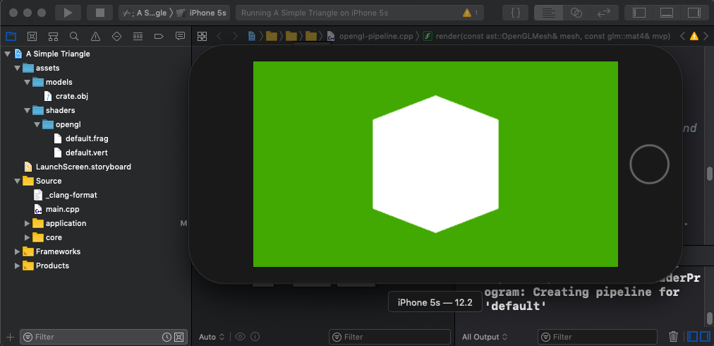
Are you ready to see the fruits of all this labour?? Run your application and our cheerful window will display once more, still with its green background but this time with our wireframe crate mesh displaying! Try running our application on each of our platforms to see it working.
Note: We don’t see wireframe mode on iOS, Android and Emscripten due to OpenGL ES not supporting the polygon mode command for it.
Console
MacOS

iOS
Android

Emscripten

Windows

Summary
A hard slog this article was - it took me quite a while to capture the parts of it in a (hopefully!) clear way, but we have articulated a basic approach to getting a text file from storage and rendering it into 3D space which is kinda neat.
In the next article we will add texture mapping to paint our mesh with an image.
The code for this article can be found here.
Continue to Part 11: OpenGL texture mapping.
End of part 10